

Valve technology harmful phenomena in the operation of control valve
Time:
Jan 10,2023
Author:
Source:
First of all, the harmful phenomenon is serious noise, which will affect the health of employees and the working environment. Noise is a symptom from the inside of the valve, which usually affects the durability of the equipment and even damages the equipment. The generation principle of valve noise can be divided into the following categories: mechanical, aerodynamic and hydrodynamic. Mechanical noise may be caused by vibration, resonance of parts inside the valve, inaccurate guidance of moving parts, or excessive clearance. The reason of aerodynamic noise is that the mechanical energy of compressible medium flow is transformed into sound energy. As the medium depressurizes, the released energy accelerates the flow of the fluid - usually exceeding the speed of sound - and produces noise. Hydrodynamic noise is generated by fluid flow. The specific conditions are as follows: collision between turbulence and valve and pipe wall, cavitation (cavitation) and evaporation (flash).
Cavitation (cavitation)
Cavitation always moves downstream. When the cross-sectional area of the channel becomes larger, the flow rate of the medium decreases and the pressure increases. In this case, cavitation will appear, and its internal pressure is the same as the steam pressure in the flow channel, but lower than the pressure of the surrounding medium. Then the bubble collapses inward and disappears. The formation of cavitation, the blocking flow caused by cavitation, and the subsequent collapse and disappearance of cavitation downstream are the so-called cavitation phenomenon. When the bubble collapses, it will make a loud noise. The noise made by countless bubble collapses is like countless gravel passing through the valve. This kind of noise is so loud that people who have been affected by it for a long time may even damage their hearing. In addition, shock waves will be generated when cavitation collapses, which may cause serious damage to the valve.
Flash
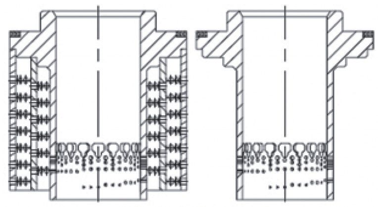
Figure 2 Porous cage valve core of control valve
In addition to collapsing and disappearing, cavitation may also become larger. As a result, the liquid with cavitation will quickly change into steam containing fine droplets, which is the flash phenomenon. The damage caused by flash is completely different from that caused by cavitation. It may cause hidden smooth grooves in parts. The mechanism of this damage is similar to that of sand blasting. Downstream of the constriction, the fluid contains a large amount of steam and a large number of fine droplets. When the liquid evaporates, the volume will increase greatly, so the downstream flow rate may reach hundreds of feet per second, and high-speed droplets may erode the valve parts. Flash damage usually does not occur instantaneously like cavitation.
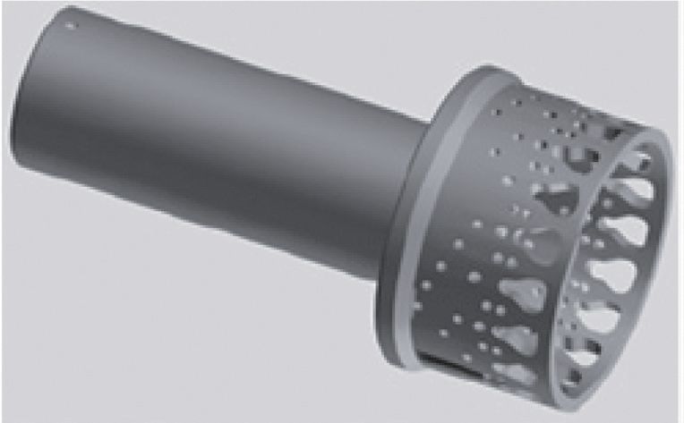
Figure 3 Porous plug of control valve
Solution
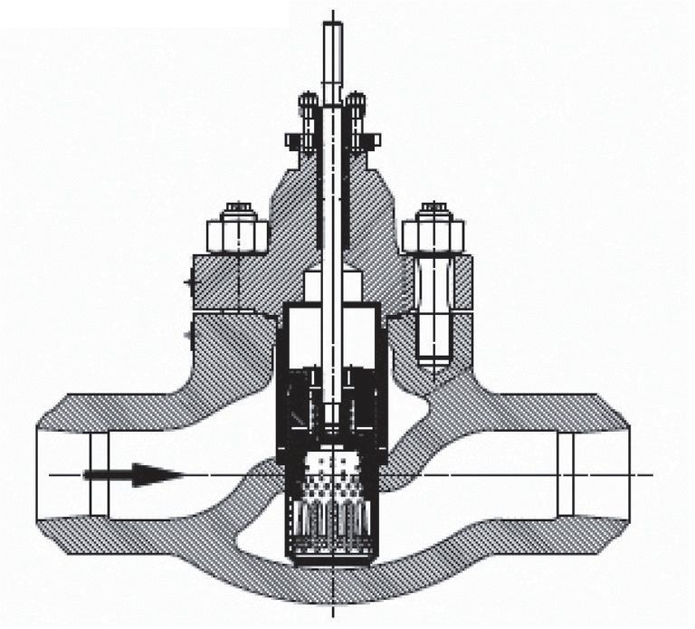
As mentioned above, various harmful phenomena will affect the performance and service life of the control valve. Therefore, our "smart valves" product family has launched a number of targeted solutions. For example, one way to reduce noise is to adopt cage structure and set matching clearance according to valve working conditions. As shown in Figure 1. The most important and efficient way to reduce aerodynamic noise is that the valve adopts the control part with hole, For example, the perforated cock (Fig. 2) or the perforated cage valve core (sleeve) (Fig. 3). Another method is to reduce the medium flow rate at the outlet end. In order to achieve this, the most common measure is to use the perforated cage valve core, orifice plate or diffuser to increase the outlet port pressure by using their choke effect. If the noise is very serious, it is necessary to use all the above measures at the same time (Figure 4).

Figure 4 The mute plate at the outlet end of the control valve can reduce the noise
In addition, there is another method that has been verified in use: apply Stellite protective layer to some or all surfaces of valve cock and valve seat by using thermal spraying, diffusion or plasma nitriding technology to make the surface of parts ca.0 The hardness within 1mm reaches 950hv, or the hardness reaches 55HRC by heat treatment. The core design of anti bubble valve is multi-stage cock (Fig. 5). The principle of preventing cavitation of multi-stage cock is that the pressure drop at each stage of the cock is controlled below the critical value. However, the disadvantage of this design is that it is difficult to effectively ensure the effective choke of each stage cock when the valve is first opened. Therefore, we adopt surface formed multi-stage cock with hole. Its structure has active characteristics and can provide different resistance according to the valve opening , it also has passive characteristics, that is, the choke effect of perforated cage valve core and orifice plate (Fig. 6).
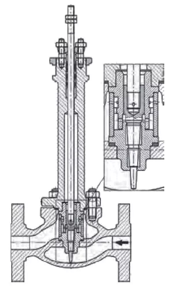
Figure 5 Anti bubble valve suitable for small flow
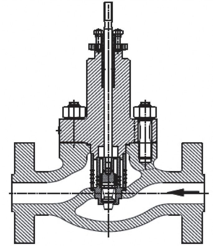
Figure 6 Multistage anti bubble valve with different choke structures
The occurrence of flash is determined by various fluid parameters, and can not be completely eliminated by design. But the destructive effect of flash can - and must - be completely eliminated. In addition to the above methods to improve the durability of valve components, "smart valves" can also apply hard coatings on the surface of the valve body and provide corrosion-resistant gaskets (Fig. 7); angle valves (Fig. 8); and valves with protective cage spool (Fig. 9).
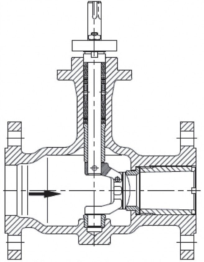
Figure 7 Plug valve for flash operation
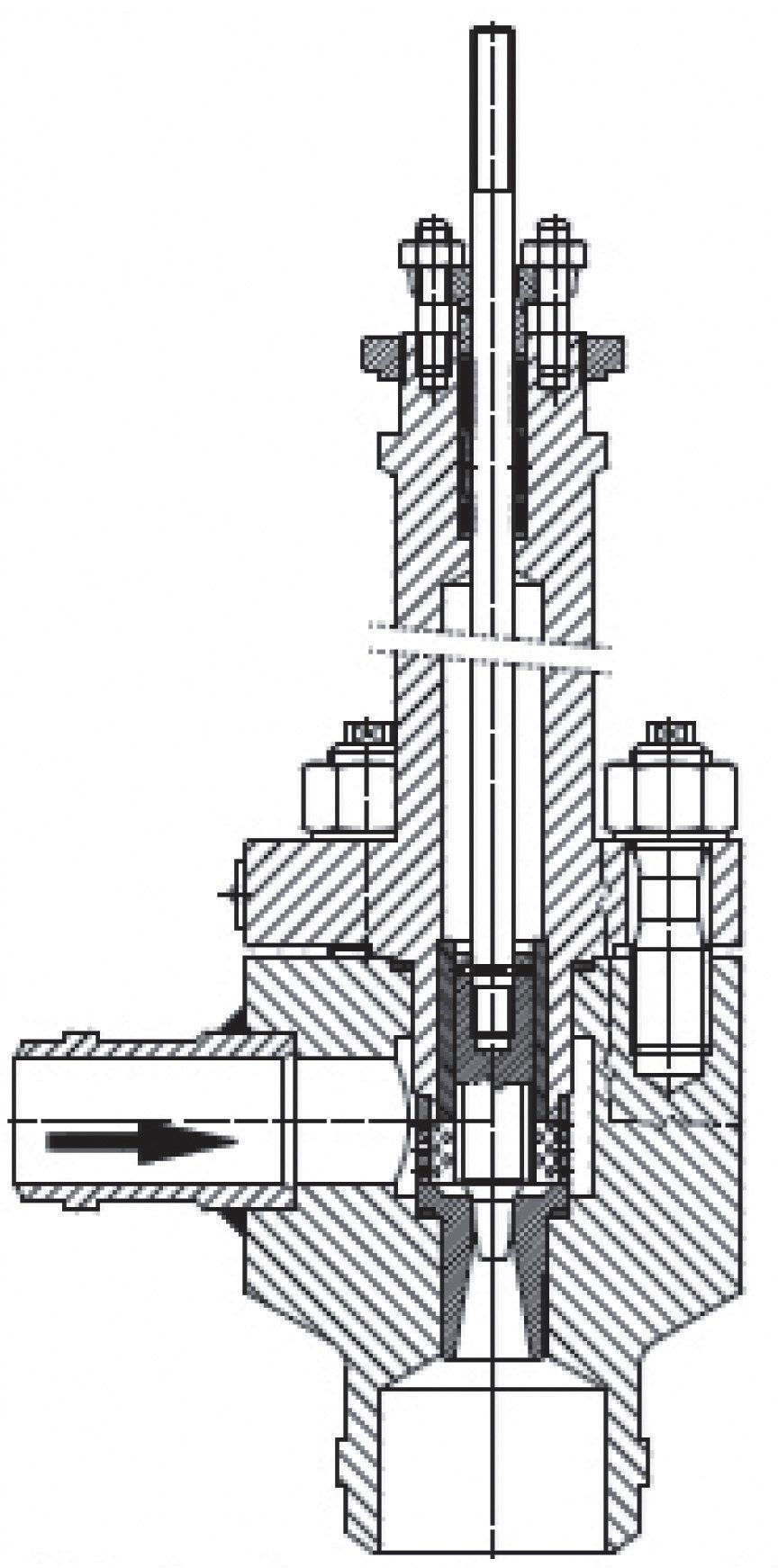
Figure 8 Angle valve for flash operation

SEARCH CONTENT
Please enter the search keywords below to search for the products you are interested in
Arnos welcome new and regular customer for visiting!